MELSERVO-J4 Series Servo Amplifier Features - Harmony with Machine


Industry-Leading Basic Performance
Industry-Leading Level of Servo Amplifier Basic Performance 
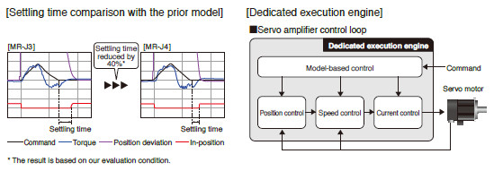
A speed frequency response of 2.5 kHz is achieved by applying our original high-speed servo control architecture evolved from the conventional two-degrees-of-freedom model adaptive control to the dedicated execution engine. Together with a high-resolution absolute position encoder of 4,194,304 pulses/rev, fast and accurate operation is enabled. The performance of the high-end machines is utilized to the fullest.
Improving Machine Performance with High-Performance Servo Motors
With improved processing speed, the rotary servo motors equipped with a high-resolution encoder enables high-accuracy positioning and smooth rotation.
Advanced Servo Gain Adjustment Function
One-Touch Tuning 
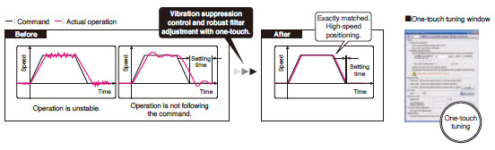
Just turn on the one-touch tuning function to complete servo gain adjustment automatically, including machine resonance suppression filter, advanced vibration suppression control II *1 , and robust filter for maximizing your machine performance. This function also sets responsivity automatically, while the real-time auto tuning requires manual setting. Moreover, a new method *2 allows to create an optimum tuning command inside the servo amplifier.
- *1. The advanced vibration suppression control II automatically adjusts one frequency.
- *2. This new method is supported by MR-J4-B/MR-J4W_-B/MR-J4-A.
Advanced Vibration Suppression Control II 
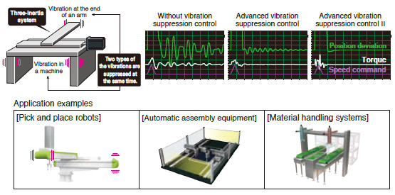
The advanced vibration suppression control II suppresses two types of lowfrequency vibrations, owing to vibration suppression algorithm which supports three-inertia system. This function is effective in suppressing residual vibration with relatively low frequency of approximately 100 Hz or less generated at the end of an arm and in a machine, enabling a shorter settling time.
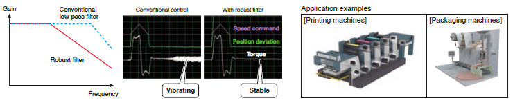
Robust Filter
Achieving both high responsivity and stability was difficult with the conventional control in high-inertia systems with belts and gears such as printing and packaging machines. Now, this function enables the high responsivity and the stability at the same time without adjustment. The robust filter gradually reduces the fluctuation of torque in a wide frequency range and achieves more stability as compared to the prior model.
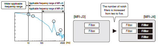
Expanded Machine Resonance Suppression Filter
With advanced filter structure, applicable frequency range is expanded from between 100 Hz and 4500 Hz to between 10 Hz and 4500 Hz. Additionally, the number of simultaneously applicable filters is increased from two to five, improving vibration suppression performance of a machine.
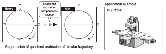
Lost Motion Compensation Function
This function suppresses quadrant protrusion caused by friction and torsion generated when the servo motor rotates in a reverse direction. Therefore, the accuracy of circular path will be improved in trajectory control used in XY table, etc.
- * This function is not supported by MR-J4W2-B and MR-J4W3-B.
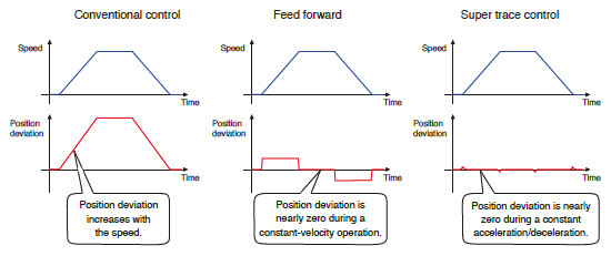
Super Trace Control
This function reduces a position deviation to nearly zero not only during constant-velocity operation, but also during constant acceleration/deceleration. The trajectory accuracy will be improved in high-rigidity machines.
* This function is not supported by MR-J4W2-B and MR-J4W3-B.
A Variety of Functions for Various Applications
* Use a compatible controller.
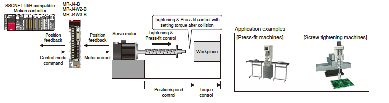
Tightening & Press-Fit Control 

This function switches position/speed control mode to torque control mode smoothly without a stop or a sudden change in speed and torque, and thus reduces load to a machine. This function is best suit for an application where control is switched from position to torque such as Tightening & Press-fit control or insertion of a work, and cap or screw tightening.
* This function is supported by MR-J4-B/MR-J4W2-B/MR-J4W3-B.
- *1. This function is not supported by MR-J4W2-0303B6.
- *2. Use corresponding servo amplifier (MR-J4-GF/MR-J4-GF-RJ/MR-J4-B/MR-J4-B-RJ) for load-side encoder.
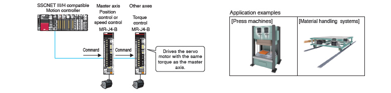
Driver Communication Function 
The controller controls the master axis by using the driver communication function of MR-J4-B servo amplifiers. The servo amplifier of the master axis transmits the torque data to the other servo amplifiers on SSCNET III/H, and the others also drive the servo motors on the basis of the torque data transmitted from the master axis. The data is transmitted via SSCNET III/H, and thus no special wiring is necessary.
Scale Measurement Function 
The scale measurement function of MR-J4-GF/MR-J4-B/MR-J4W2-B *1 servo amplifiers *2 enables to transmit position information of a scale measurement encoder to the controller when the scale measurement encoder is connected in semi closed loop control. The data of linear or synchronous encoders are transmitted to the servo system controller via the servo amplifier, resulting in less wiring.
Applicable for Various Control and Driving Systems
Compatible Servo Motors
MR-J4 series servo amplifier operates rotary servo motors, linear servo motors, and direct drive motors as standard*.
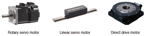
* Refer to the following for the possible combinations of servo motors and servo amplifiers.
- Combinations of Rotary Servo Motors and Servo Amplifiers
- Combinations of Linear Servo Motors and Servo Amplifiers
- Combinations of Direct Drive Motors and Servo Amplifiers
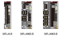
1-axis/2-axis/3-axis Servo Amplifiers
For SSCNET III/H compatible servo amplifiers, 2-axis and 3-axis types are available in addition to 1-axis type, enabling flexible systems based on the number of control axes.
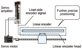
Supporting Fully Closed Loop Control
Supporting a fully closed loop control system *1 as standard, MR-J4-GF/MR-J4-B/MR-J4-A servo amplifiers enable further precise positioning *2 .
- *1. MR-J4-GF/MR-J4-B/MR-J4-A servo amplifier is compatible with two-wire type serial linear encoders. For four-wire type serial and pulse train interface (A/B/Z-phase differential output type) linear encoders, use MR-J4-GF-RJ/MR-J4-B-RJ/MR-J4-A-RJ.
- *2. Some models do not support a fully closed loop control system. Refer to "Product lines" in the catalog.
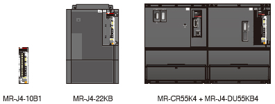
Wide Range of Power Supplies and Capacities
Each servo amplifier supports the following main circuit power supplies:
MR-J4-B/MR-J4-A: 3-phase 200 V AC/400 V AC,
1-phase 100 V AC, and 48 V DC/24 V DC
They also support a wide range of capacities from 30 W* to 55 kW.
MR-J4-GF: 3-phase 200 V AC/400 V AC, 1-phase 100 V AC
MR-J4-GF-RJ/MR-J4-B-RJ/MR-J4-A-RJ also supports DC power input.
* Servo amplifier of 30 W supports a power supply of 48 V DC/24 V DC.
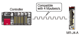
Maximum Command Pulse Frequency
General-purpose interface compatible MR-J4-A servo amplifier supports maximum command pulse frequency of 4 Mpulses/s (when differential receiver is used).
When open collector is used, both sink and source inputs are enabled.
Built-in Positioning Function for Simple System
MR-J4-GF(-RJ) and MR-J4-A-RJ with Built-in Positioning Function
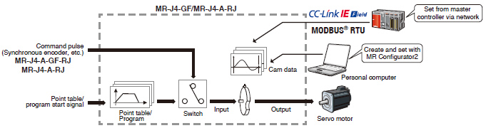
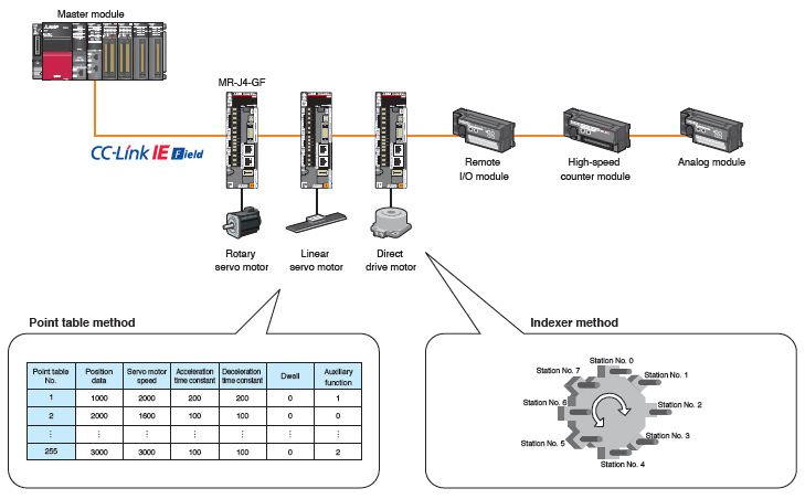
MR-J4-GF(-RJ) and MR-J4-A-RJ have a built-in positioning function, enabling positioning operation with point table, program-based*, and indexer methods. With these servo amplifiers, a positioning system is configured without a Positioning module (command pulse). Positioning command is executed by CC-Link IE Field network, input/output signals, or RS-422/RS-485 communication (up to 32 axes). MR Configurator2 allows easy setting of the positioning data.
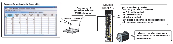
* The program-based method is supported only by MR-J4-A-RJ.
Point table method

Set position data (target position), servo motor speed, and acceleration/deceleration time constants in point table. Setting the point table data (settable up to 255 points) is as easy as setting parameters. Perform positioning operation with a start signal after selecting the point table Nos.
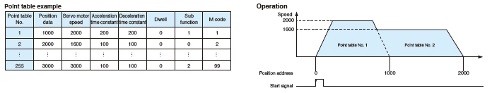
* For MR-J4-A-RJ, point table can be set with push buttons on the servo amplifier or with MR-PRU03 parameter unit.
Program method*

Create positioning programs with dedicated commands, and perform positioning operation with a start signal after selecting the program Nos. The program-based method enables more complex positioning operation than the point table method. Maximum of 256 programs are settable. (The total number of steps of all programs: 640)
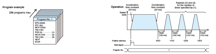
* MR Configurator2 is required to create programs.
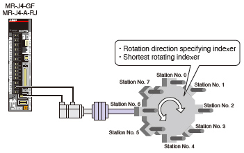
Indexer method*
Perform positioning operation by specifying equally divided stations (up to 255 stations) and the number of gear teeth on machine and motor sides. The travel distance will be calculated automatically based on the number of equally divided stations set in the parameter. The positioning operation is performed with a start signal after the station position Nos. are selected.
Rotation direction specifying indexer or shortest rotating indexer can be set.
* Fully closed loop control mode and linear servo motor control mode are not supported by the indexer method.
New Useful Functions with Positioning Function
* Not supported by MR-J4-03A6-RJ.
New useful functions are added to the positioning function: simple cam function, encoder following function, pulse input through function, simple cam position compensation function, and communication functions (MODBUS ® RTU, Point to Point positioning, and current position latch function). Apply these useful functions to a wide variety of applications to configure positioning system easily.
Simple cam function
Various patterns of cam data are created easily with MR Configurator2. Command pulse or point table/program start signal is used as input to the simple cam. The input command will be outputted to the servo motor according to the cam data.
* The program-based method is supported only by MR-J4-A-RJ.
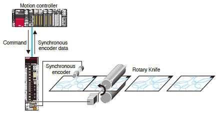
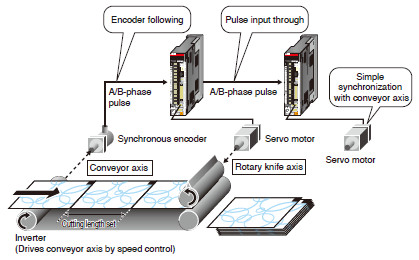
Encoder following function/Pulse input through function*

With the encoder following function, the servo amplifier receives A/B-phase output signal from the synchronous encoder as command pulse, and the input command will be outputted to the servo motor according to the cam data. Setting cam data that matches with the sheet length, a circumference of the rotary knife axis, and the synchronous section of the sheet enables a system in which the conveyor axis and the rotary knife axis are synchronized. Up to 4 Mpulses/s of input from a synchronous encoder is compatible with the servo amplifier. The pulse input through function allows the first axis to output A/B-phase pulses which are received from the synchronous encoder to the next axis, enabling a system in which the subsequent axes are synchronized with the synchronous encoder.
* The pulse input through function is available as A/B-phase pulse input through function for MR-J4-GF-RJ and as command pulse input through function for MR-J4-A-RJ.
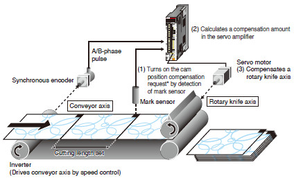
Simple cam position compensation function*
The actual position of the servo motor is obtained based on the inputs from the sensor that detects the registration marks printed on the high-speed moving film. The servo amplifier calculates compensation amounts and corrects position errors of the rotary knife axis based on those inputs from the sensor so that the film can be cut at the set position.
* "Cam position compensation request" is turned on with touch probe input for MR-J4-GF-RJ and mark sensor input for MR-J4-A-RJ.
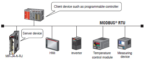
Communication function (MODBUS ® RTU)
In addition to RS-422/RS-485 communication (Mitsubishi Electric general-purpose AC servo protocol), RS-485 communication (MODBUS ® RTU protocol) is supported. MODBUS ® RTU protocol is compatible with function code 03h (Read holding registers), etc.
Controlling and monitoring of the servo amplifier is possible by external devices.
* RJ-45 junction connector terminal block and RJ-45 compatible cable designed for MR-J4-A-RJ are required.
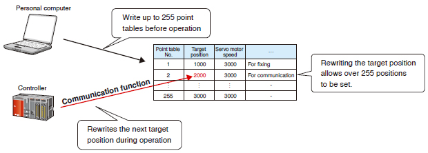
Communication function (Point to Point positioning)
Up to 255 points of Point to Point positioning are enabled when the target position is set in the point table in advance. Rewriting the next target position during an operation is also possible by the communication function.
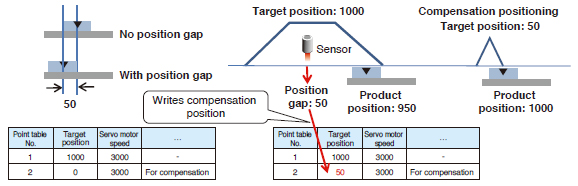
Communication function (current position latch)
Based on the data latched by the mark detection function (current position latch*), a target position is compensated by being written in the point table.
* When the mark detection signal turns on, a current position will be latched, and the latched data will be read with the communication function.
- Example: Executing positioning compensation when a product is mispositioned by 50 on a handling pallet.
- Start an operation by specifying point table No. 1 (target position: 1000).
- Communication function (current position latch) measures a position gap with the mark detection function and writes the position gap of 50 to the target position in point table No. 2 for compensation during the operation.
- After the operation of point table No. 1 is completed with a position gap of 50, start the operation by specifying point table No. 2. The product will be set to the right position.
All-Rounder Network with CC-Link IE Field
All-in-One Network
The network is designed to simultaneously handle distributed control, I/O control, and motion control. CC-Link IE Field Network lets you connect field devices such as programmable controllers, I/O modules, high-speed counter modules, servo amplifiers, inverters, and displays, providing optimal network which best fits the needs of the application.
Choose from star, line, or ring * topology suitable for layout of lines and machines.
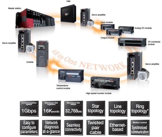
* The Simple Motion modules do not support a ring topology.
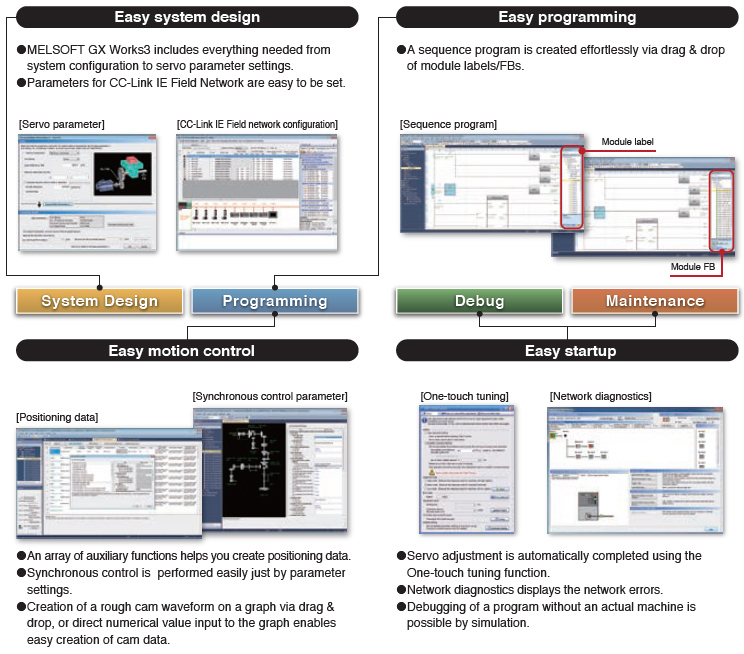
All-in-One Engineering Software
This all-in-one MELSOFT GX Works3 covers all aspects of the product development cycle from system design to maintenance - including programming, setting of CC-Link IE Field Network and Simple Motion modules, and adjustment of servo amplifiers.

All-Rounder Driving System with CC-Link IE Field
Compatible with CC-Link IE Field Network
MR-J4-GF(-RJ) is compatible with CC-Link IE Field Network as standard.
The servo amplifier is connectable with Ethernet-based CC-Link IE Field Network, enabling high-speed, seamless communication.
Easy Positioning with CC-Link IE Field Network
A combination of a master module and MR-J4-GF(-RJ) allows positioning operation with point table method or indexer method, not requiring a Positioning module. With the point table method, just set the point table No. and turn on the start signal, and then the positioning operation will be started. A continuous operation of the next point table is also possible without stopping.
In the indexer method, the travel amount is automatically calculated based on the number of stations set in the parameter.
For more details of the positioning function, refer to " Positioning Function ".
CC-Link IE Field Network Motion Control
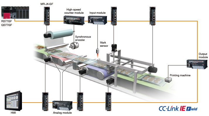
A combination of a Simple Motion module and MR-J4-GF(-RJ) enables high-performance synchronous control and interpolation control with simple parameter setting and a start from a sequence program. Speed control and torque control are also possible, suitable for converting machines. In addition, using remote inputs/outputs which are compatible with the synchronized communication function enables a system synchronized with the command cycle of the servo amplifier.
An example of inputs/outputs synchronized with the command cycle of the servo amplifier
A synchronous encoder, unwinder, printing machine can be synchronized with the servo command communication cycle.
Supporting CC-Link IE Field Network Basic *3 
With recent trends of IoT *1 , network connection of devices and equipment for small-scale systems are becoming more mainstream. CC-Link IE Field Network Basic realizes easier network integration of Ethernet devices, as its cyclic communications stack is software-based, without requiring a dedicated ASIC helping to reduce implementation costs for device partners.
Transparent communications are achieved by utilizing SLMP *2 that enables seamless connectivity within all levels of manufacturing.
- *1. Internet of Things
- *2. Seamless Message Protocol
- *3. CC-Link IE Field Network Basic is supported by MR-J4-GF with software version A4 or later.
Refer to the Instruction Manual for CC-Link IE Field Network Basic.
![三次元板金展開システム CamMagic SMOPlus [SpaceClaimSMOPlus]](assets/img/mc_i62.jpg)
High-Response Servo System Achieved with SSCNET III/H
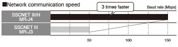
Three Times Faster Communication Speed
Communication speed is increased to 150 Mbps full duplex (equivalent to 300 Mbps half duplex), three times faster than the conventional speed. System response is dramatically improved.
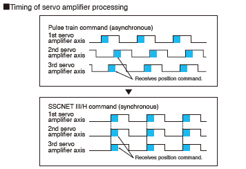
Synchronous Communication
Synchronous communication is achieved with SSCNET III/H, offering technical advantages for machines in printing and food processing industry that require deterministic control.
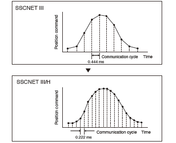
Cycle Time as Fast as 0.222 ms
Smooth control of a machine is possible using high-speed serial communication with a cycle time of 0.222 ms.
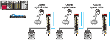
Improved Noise Tolerance by Optical Communication
The fiber-optic cables thoroughly shut out noise that enters from the power cable or external devices. Noise tolerance is dramatically improved as compared to metal cables.
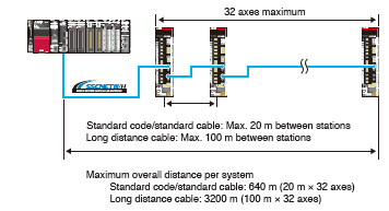
Long Distance Wiring up to 3200 m 
Long distance wiring is possible up to 3200 m per system (maximum of 100 m between stations × 32 axes), suitable for large-scale systems.
* This is when all axes are connected via SSCNET III/H.
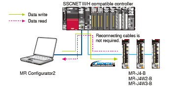
Central Control with Network
Large amounts of servo data are exchanged in real-time between the controller and the servo amplifier.
Using MELSOFT MR Configurator2 on a personal computer that is connected to the Motion controller or the Simple Motion module helps consolidate information such as parameter settings and monitoring for the multiple servo amplifiers.
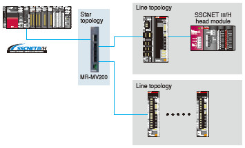
Network Topology
Star and line topologies are available with MR-MV200 optical hub unit* through SSCNET III/H for a network configuration. Maintenance can be executed without stopping the whole system, and thus the operation rate will be increased.
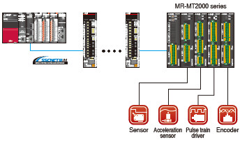
I/O Signals Synchronized with Motion Control
MR-MT2000 series sensing modules including the I/O module, analog I/O module, pulse I/O module, and encoder I/F module are connected to SSCNET III/H.
These various modules enable a faster, more accurate machine operation by synchronizing the I/Os of a general-purpose pulse train driver, sensor, and SSI encoder with the motion control.
* For MR-MV200 optical hub unit and MR-MT2000 sensing module, refer to