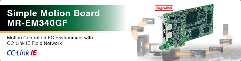
Simple Motion Board Features

MR-EM340GF
- Concept
- CC-Link IE Field Network
- Numerous Motion Control Functions
- Direct control
- Event history
- Software Development Kit
- Servo Amplifier MR-J4-GF
- Functions List
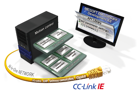
Concept
Numerous motion control functions, such as positioning, synchronous control, and speed-torque control are performed by the Simple Motion board being embedded in a PC which supports PCI Express ® .
- Various field devices, such as servo amplifiers, I/O modules, and high-speed counter modules are connected flexibly with the same network.
- The Simple Motion board functions as a master station of CC-Link IE Field Network.
- The interrupt function via PCI Express ® enables an event-driven program to be created with Visual C++ ® .
-
Numerous motion control
functions on PC environment -
Easy programming and increased efficiency in debugging with engineering software
-
Seamless integration of Mitsubishi Electric's servo system into one network
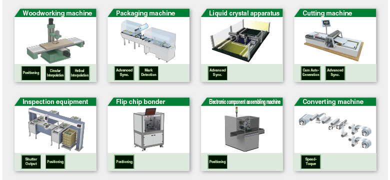
Application Examples
Selecting the best suitable control methods and functions for your machine achieves an optimal solution.
CC-Link IE Field Network


All-in-One Network
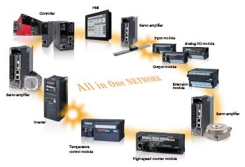
CC-Link IE Field Network - Integration of IA components on
ONE single network
CC-Link IE Field Network is a single network which combines the versatility of Ethernet and highly accurate synchronous operation for Motion control.
With the single network, various field devices, such as servo amplifiers, I/O modules, and high-speed counter modules, are connected with no restriction.
All-in-One Engineering Software
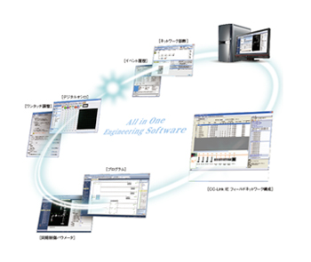
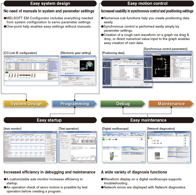
Covering all aspects of the product development cycle - From Easy Settings to Diagnosis with ONE engineering software
To meet customer needs, such as easy programming, easy startup, and easy maintenance, we offer the All-in-One engineering software as an easy manipulation tool with various new functions and technology.
Various tasks, such as Simple Motion parameter settings, servo adjustment, and debugging, are performed only with this All-in-One engineering software.
Synchronization of Inputs and Outputs with Servo Control
In a single network, inputs/outputs are synchronized with the command communication cycle of the servo amplifier. For example, an input from a synchronous encoder and an output to a printing machine are synchronized in the same network. CC-Link IE Field Network enables a wide range of Motion control applications.
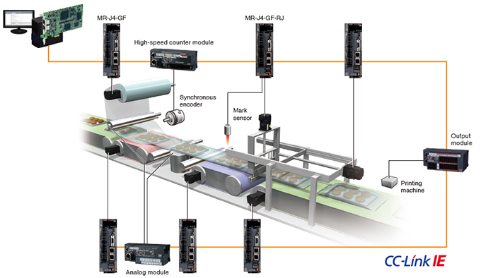
[An example of inputs and outputs synchronized with the command communication cycle of a servo amplifier]
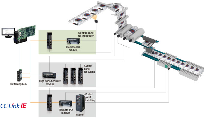
Flexible network topology
Star, line, and star/line mixed topologies are available for a network configuration by using a switching hub. An easy topology created only by a cable being connected to a free port of the switching hub allows field devices to be added to the system more flexibly.
Numerous Motion Control Functions
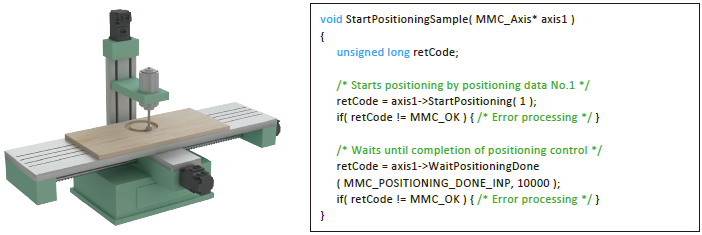
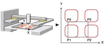
Positioning Control
- To respond to various application needs, the Simple Motion board offers various control functions, such as linear interpolation, 2-axis circular interpolation, fixed-pitch feed, and continuous trajectory control.
- Automatic operation can be executed easily by setting positioning addresses, speeds, and other setting items with the API library.
- Powerful sub-functions, such as M-code output, skip, speed change, and target position change, are available.
■ Helical interpolation
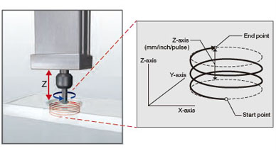
Helical interpolation draws a helical path by a linear interpolation axis (Z-axis) following to 2-axis circular interpolation control (X-axis and Y-axis). For applications that require the boring of deep, large holes, usually the helical interpolation of the three axes must be taken into consideration.
- Milling is done in a circle, with the X and Y axes synchronized to achieve the pre-set size.
- The depth of the hole is simultaneously controlled along the Z axis, ensuring minimal deviation in the cutting bit position.
■ Block-start
Just with a one-time start, the operation is carried out sequentially following the multiple positioning data. This control is suitable for machines requiring the same operation repeated.
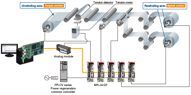
Speed-Torque Control
Speed control follows speed commands to keep the speed constant, and torque control follows torque commands to keep the torque constant. The Simple Motion board can be used for the speed-torque control, such as unwinding or rewinding.
Positioning using absolute position coordinates can be smoothly performed even after switching back to position control because the current position is controlled during the speed-torque control.
Advanced Synchronous Control
The advanced synchronous control is software-based synchronous control as an alternative to mechanical control, such as gear, shaft, clutch, speed change gear, and cam. In addition, a cam is easily generated with cam auto-generation function. The synchronous control can be started and ended for each axis, allowing the synchronous control axis and positioning control axis within the same program.
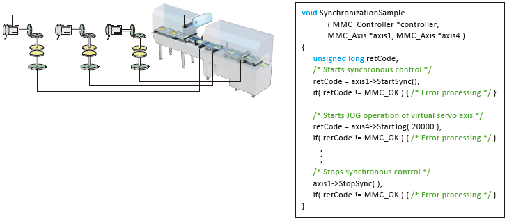
■ Cam auto-generation
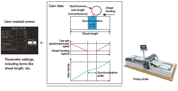
Cam data for a rotary cutter can be generated automatically simply by parameter settings of sheet length, synchronization width, cam resolution, etc.
Direct control
The direct control is a function that controls servo amplifiers directly by transmitting set command positions for each operation cycle from a user program to the servo amplifiers.
- The direct control can be combined with positioning control.
- Control can be switched between the direct control and the positioning control.
- A personal computer with a real-time operating system can perform fixed-cycle Motion control using interrupts at every operation cycle.
- Thanks to the position command buffers of up to 16 phases, even non-real-time operating system (Windows ® ) can perform at 0.5 ms (the fastest rate) cycle command operation; This enables further increase in accuracy in trajectory control.
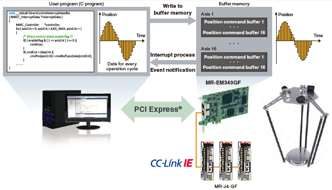
(Note): Execute coordinate conversion of a parallel link robot with a user program.
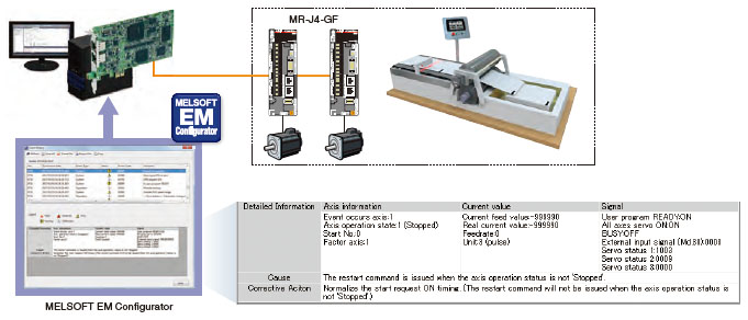
Event history
Events occurred on each remote device and servo amplifiers can be stored to the Simple Motion board. Information of "WRITE" operation to the program, error occurrence, etc. is listed chronologically, enabling an investigation of the cause of the error and a prompt restoration of servo amplifiers.
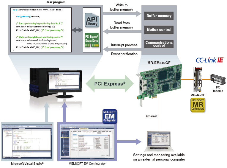
Software Development Kit MELSOFT EM Software Development Kit
MELSOFT EM Software Development Kit is a development software package, supporting the engineering process from system design and programming to debug and maintenance for the Simple Motion board.
MELSOFT EM Configurator
Every step in the engineering process from system design and programming to debug and maintenance, is supported by this software.
MELSOFT MR Configurator2
Primarily, tuning, monitoring, and diagnosis are easily performed with this software by being connected to a servo amplifier.
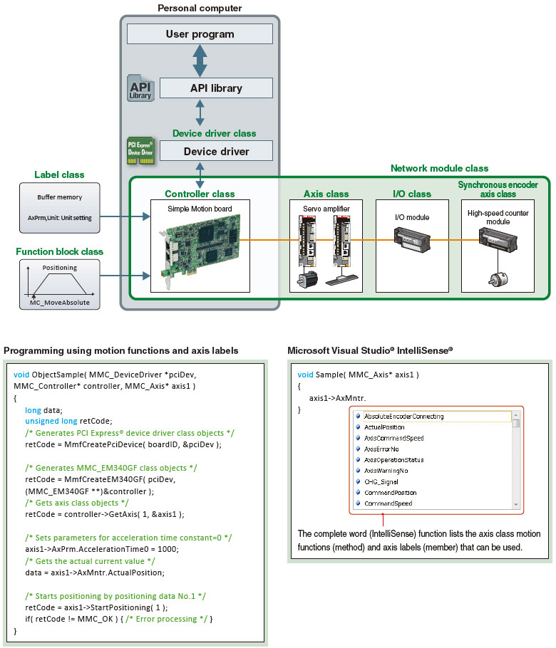
API library
The API library is an add-on library which uses functions (method) and labels (member) of controller and axis classes, and enables easy programming with Visual C++ ® .
PCI Express ® device driver
The PCI Express ® device driver is software for a user program to gain access to the Simple Motion board via PCI Express ® .
(Note): Contact your local sales office for the latest version of Software Development Kit.
Development and Debugging Environments
A user program is created by adding the API library (for motion control) to a project of Microsoft Visual Studio ® .
• INtime ® and RTX (real-time operating system) are supported.
- (Note): Contact your local Mitsubishi Electric office for more details.
(Note): OS and the development environment are not included.
MELSOFT EM Configurator (Setting Tool for Simple Motion Board)
API library (C++ motion class library)
With the C++ motion class library, a program is created using functions (method) and labels (member) of controller and axis classes, and other classes.
- The class library creates the program with high readability.
- Coding time is reduced with Microsoft Visual Studio ® IntelliSense ® .
- Compatibility with event-driven programming is improved by specifying any bit data as a condition of interruption.
- The library with the same interface specifications as PLCopen ® Motion Control FB, is available and suitable for fixed-cycle programming.
[Conception diagram of class types in C++ motion class library]
CC-Link IE Field Network Servo Amplifier MR-J4-GF
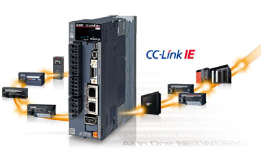
CC-Link IE Field Network servo amplifiers achieve an optimal solution and improve productivity in combination with the Simple Motion board.
- Industry-leading basic performance
Industry-leading levels of servo amplifier basic performance shorten a machine cycle time. - Advanced servo gain adjustment
The advanced vibration suppression control function is easily used for maximizing your machine performance. - A wide range of product series and capacities
From rotary to linear and direct drive motors, a wide range of servo motors are available, significantly improving your machine performance. - Preventive maintenance
The data inside a servo amplifier are read via the network, and used for preventive maintenance, such as machine diagnostics.
■Control mode
Two types of modes are available according to your needs:
- Motion mode for a wide range of motion control functions, such as multiple-axis positioning, synchronous control, etc.
- I/O mode for single-axis positioning
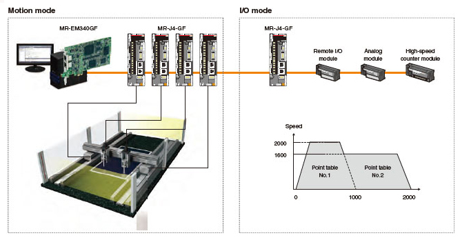
This mode enables advanced motion control functions, such as multi-axis positioning, synchronous control, and speed-torque control in combination with the Simple Motion board.
This mode easily drives a belt conveyor, a rotary table, a ballscrew mechanism, etc.
by using the built-in positioning function in a servo amplifier.
Functions List
| Simple Motion board | |||||
|---|---|---|---|---|---|
| MR-EM340GF | |||||
| Maximum number of control axes (virtual servo amplifier axis included) |
16 axes | ||||
| Servo amplifier connection system | CC-Link IE Field Network | ||||
| Maximum distance between stations [m(ft.)] | 100(328.08) | ||||
| Connectable servo amplifier | MR-J4-GF, MR-J4-GF-RJ | ||||
| Operation cycle (operation cycle settings) | 0.5 ms, 1.0 ms, 2.0 ms, 4.0 ms | ||||
| Engineering Environment | MELSOFT EM Software Development Kit | ||||
| Control modes | Positioning, Trajectory control (linear, arc, and helical), Speed control, Speed-torque control | ||||
| Control unit | mm, inch, degree, pulse | ||||
| Number of positioning data | 600 data/axis | ||||
| Acceleration/deceleration process | Trapezoidal acceleration/deceleration, S-curve acceleration/deceleration | ||||
| Manual control | JOG operation, Manual pulse generator, Inching operation | ||||
| Expansion control | Direct control | ||||
| Functions that change control details | Current value change, Target position change function, Torque change function, Speed change function, Override function, Acceleration/deceleration time change function |
||||
| Home position return method | Driver home position return method | ||||
| Auxiliary functions | Forced stop function, Hardware stroke limit function, Software stroke limit function, Absolute position system, Amplifier-less operation function, Unlimited length feed, Optional data monitor function, Mark detection function, Flash ROM backup, M-code output function, Event history function, Digital oscilloscope function, Cam auto-generation function |
||||
| Number of occupied I/O points | 32 points (I/O allocation: Intelligent function module, 32 points) | ||||
| Current consumption [A] | 12 VDC | 0.4 | |||
| 3.3 VDC | 0.6 | ||||
| Mass [kg] | 0.13 | ||||
Performance specifications of CC-Link IE Field Network
| Simple Motion module | |||
|---|---|---|---|
| MR-EM340GF | |||
| Maximum link points per network | RX | 16k points (16384 points, 2 kbytes) | |
| RY | 16k points (16384 points, 2 kbytes) | ||
| RWr | 8k points (8192 points, 16 kbytes) | ||
| RWw | 8k points (8192 points, 16 kbytes) | ||
| Maximum link points per station | Master station | RX | 16k points (16384 points, 2 kbytes) |
| RY | 16k points (16384 points, 2 kbytes) | ||
| RWr | 8k points (8192 points, 16 kbytes) | ||
| RWw | 8k points (8192 points, 16 kbytes) | ||
| Local station | RX | 2k points (2048 points, 256 bytes) | |
| RY | 2k points (2048 points, 256 bytes) | ||
| RWr | 256 points, 512 bytes | ||
| RWw | 256 points, 512 bytes | ||
| Intelligent device station | RX | 2k points (2048 points, 256 bytes) | |
| RY | 2k points (2048 points, 256 bytes) | ||
| RWr | 256 points, 512 bytes | ||
| RWw | 256 points, 512 bytes | ||
| Remote device station | RX | 128 points, 16 bytes | |
| RY | 128 points, 16 bytes | ||
| RWr | 64 points, 128 bytes | ||
| RWw | 64 points, 128 bytes | ||
| Ethernet | Communication speed | 1Gbps | |
| Connection cable | 1000BASE-T Ethernet cable (Note-1) : category 5e or higher (double shielded/STP) straight cable | ||
| Maximum distance between stations [m(ft.)] | 100(328.08) (conforms to ANSI/TIA/EIA-568-B (category 5e)) | ||
| Topology | Line type, star type, line/star mixed type | ||
| Overall cable distance | Line type [m(ft.)] | 12000(39370.08) (When 1 master station and 120 remote stations are connected) | |
| Star type (Note-2) | Depends on system configuration | ||
| Maximum connectable stations per network | 121 stations (1 master station. 120 remote stations) | ||
| Maximum number of networks | 239 | ||
- (Note-1): Use the cables recommended by CC-Link Partner Association for CC-Link IE Field Network.
CC-Link IE Controller Network cables are not compatible with CC-Link IE Field Network. - (Note-2): A switching hub is required for star topology.